In Example6 and Example7, I showed how to programmatically generate 3D content and put it onto the screen using Unity Mesh components.
In those examples, we just set up vertices, indices and colours and then passed those to Mesh components. So how do the mesh components put the content onto the screen?
Well, this is where we start to look at the low-level systems that drive 3D engines and I’ll explain what’s needed and how it gets rendered
What is a 3D model?
A 3D model is a collection of Vertices, Indices, UVs, Colours, Normals, Binormals and/or Tangents. Each of these pieces give information about the model and the mapping the texture or material information onto the various surfaces of the model
Lets start with a very basic model. We’ll only use vertices for now so we can easily see the path to the display
Model, View, Projection Transforms
When moving an object into the 3D world, you’ll use a ModelViewProjection matrix. This is a combination of three transforms that are used to transform models to the screen
Model: Below is a simple model in “Model” space. i.e. The vertices are untransformed and centred around 0, 0, 0 like this…

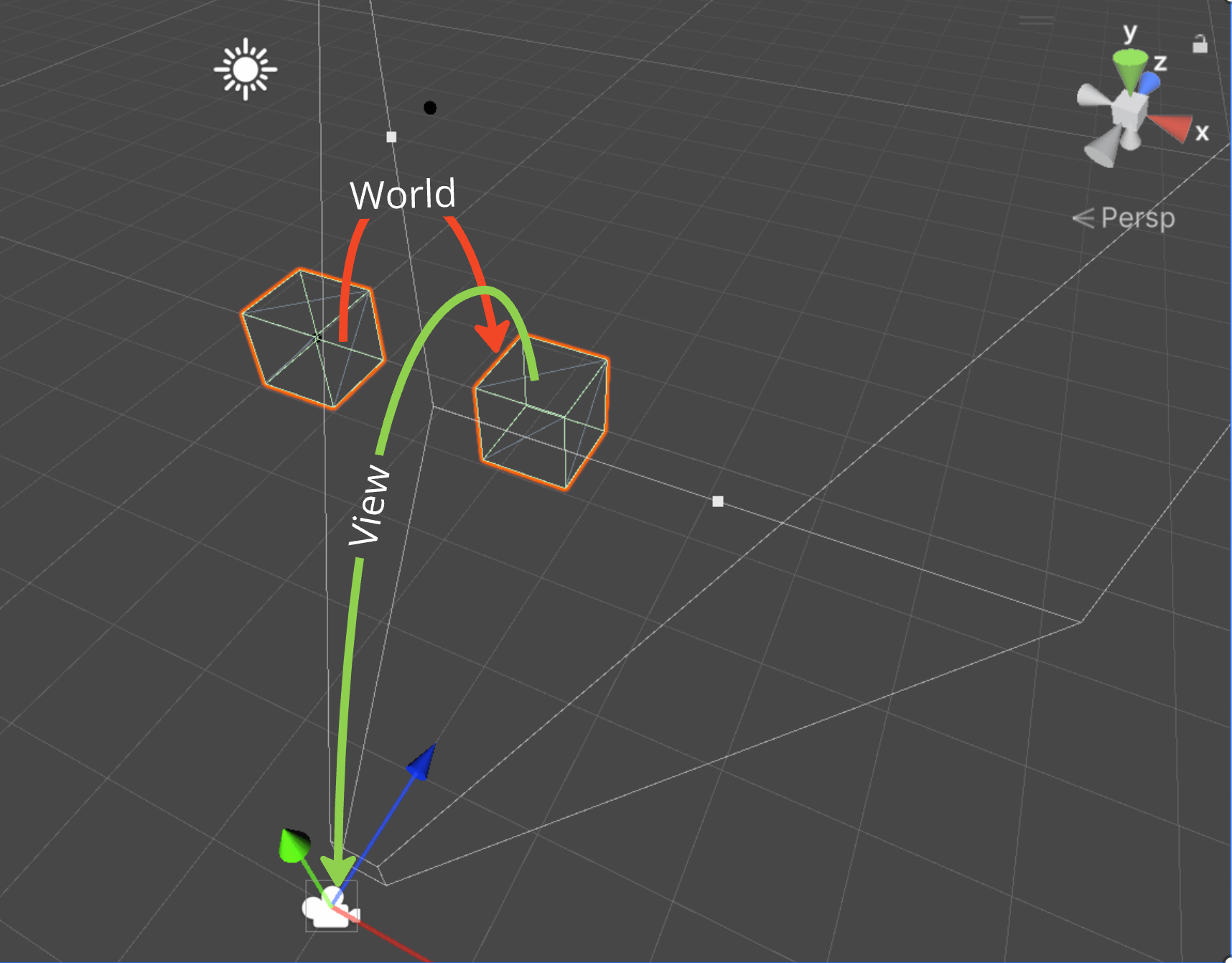
In order to display this cube, we want to move the model into “World” space. This means that we’re moving the object to its final position within the 3D World (or scene)

View: Next is the “View” transform. The “View” is the transform of the camera. We put everything in the World and then we View the world from a camera position.
Projection: The last transform in the chain is the Projection transform
This transform will decide how the content of the scene is ‘distorted’ to make it look 3D
Usually, we want anything that’s further from the camera to appear smaller on the screen. This gives perspective to the scene.
The amount of the scene you see is decided by the Field of View. This is the number of degrees across the view frustum.
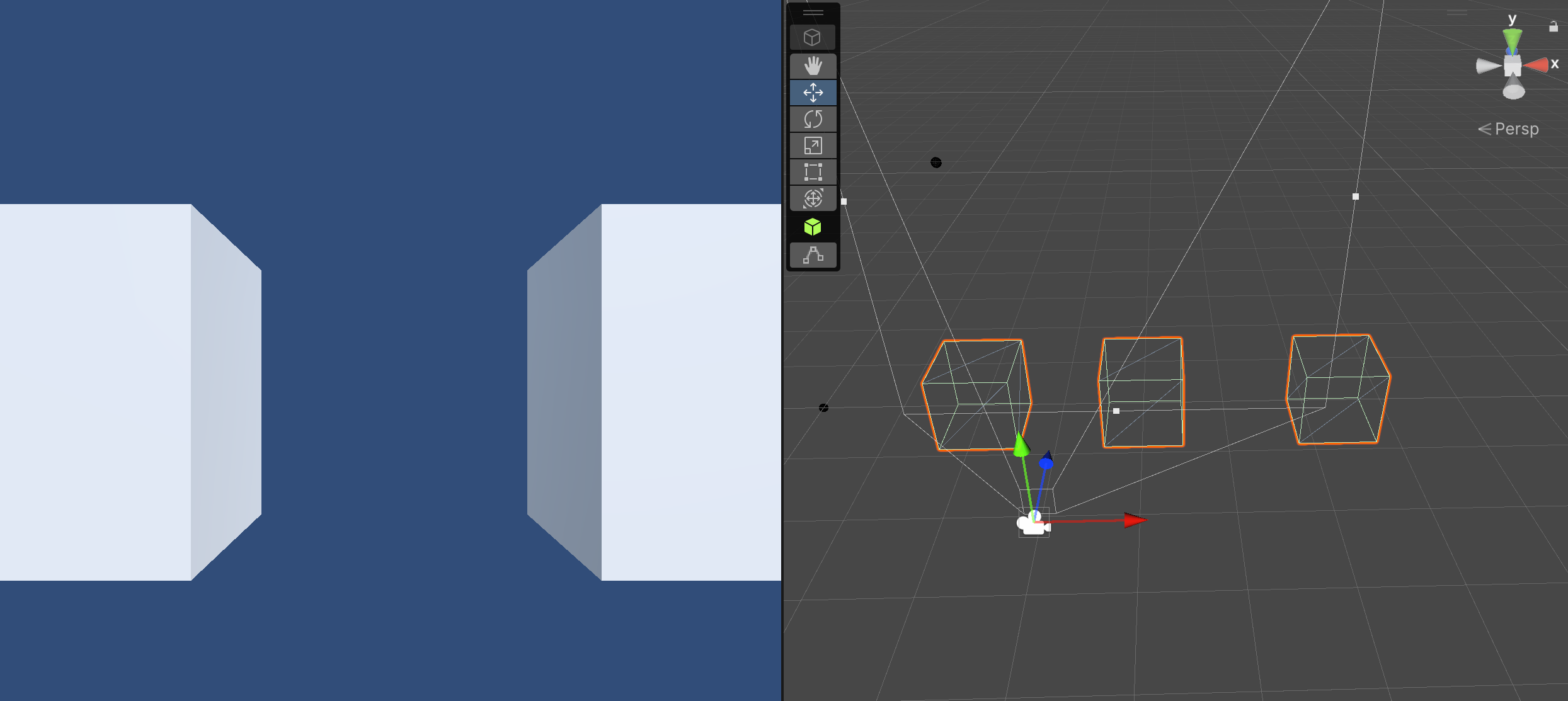
The Frustum is a visual representation of the area that the camera can see. On the diagram below (in the right-hand pane), you can see the frustum in front for the camera.
The view on the left shows what the camera actually sees (the area inside the frustum)
So, once we’ve applied the Model, View and Projection transforms then we have everything in the scene transformed to make it look 3D on a 2D plane (the screen)
…and that’s the whole process… well, in its most basic form anyway.
Next post, I’ll go into how to generate the transforms we need to complete the above process in more detail.


Leave a comment