So, I’ve set up Example07. This shows how to generate a cube programmatically and can be found on the git repo here
The code has been written to split the standard 3D from the Unity 3D to allow re-use if you’re using a custom rendering engine. You’ll see this marked in the code
Polys are flipped on the cube to keep the mesh symmetrical. This will be important in a later example and polys are also reversed to ensure the backface culling works correctly
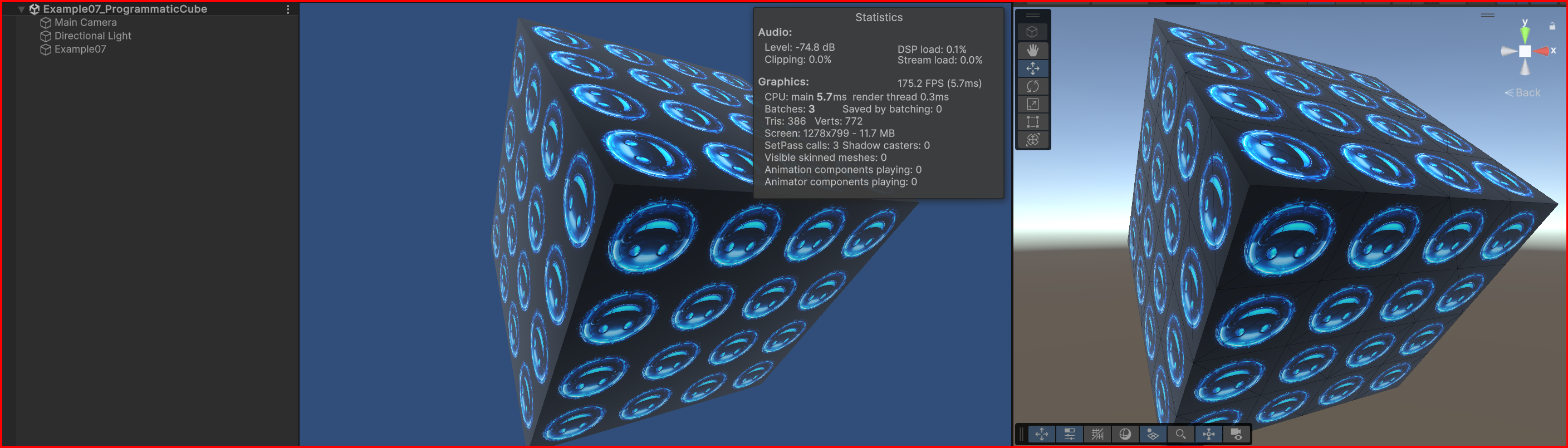
This example will give you something that looks like this…
So, let’s take a look at the code and explain what all this is doing…
The Basic Set-up
The first piece of code is just the start-up and standard stuff. We create a cube with 1m x 1m x 1m dimensions and we sub-divide each axis into 4 quads. In the above image, you can see that this gives 16 quads per surface.
We also have a simple piece of code in the Update that rotates the cube so we can see how it’s built

Building the Cube Programmatically
Next, we get to the code that sets up the cube. This first bit is just creating storage for the verts and indices and figuring out sizes for each sub-division on the surface.
The ‘pos’ is the current position of the vert we’re working on. We start in the left, top, front(-x, +y, -z)
The last bit is the start of the iteration through the surfaces. We loop through in y and x.

Adding the Vertices
Now we put the verts in place. This bit of code figures out which side of centre the verts are. This is used to decide whether we’re going to flip the verts to keep them symmetrical.
Verts are added as Top Left (TL), Top Right (TR), Bottom Right (BR) and Bottom Left (BL). We use this order to maintain a “clockwise winding order“, which is the winding order that Unity uses to determine front-facing polys
If verts are clockwise from the point of view of the camera, then Unity will display them. If they’re anti-clockwise then Unity will assume they’re facing away from the camera and nothing will be displayed (rendered)

Adding the Other Five Sides
We now repeat the adding of the verts for the other five sides of the cube. Each time we add verts we move to the position of the next side before adding the verts.
If a poly is facing in the opposite direction then we also flip the winding order (Take a look at “AddIndices” to see how that works). This allows the polys to be visible when looks at from the other side of the cube.
If we render at this stage, then we’ll see something like this…

As you can see, the polys are all radiating out from a central point on each surface. I’m going to show you how to do boolean cuts on surfaces in a later tute so the symmetrical display will become important when we do that.
Adding Colours
Next, we’re going to add some colours. This piece of code takes care of that issue…

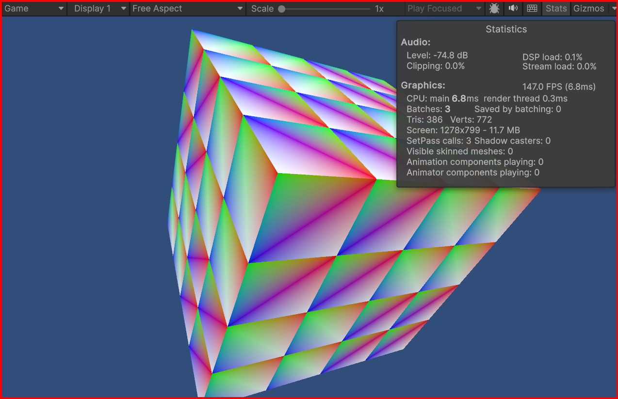
So, we add one colour for each vertex. The colours are set up as Red, Green, Blue and White (Standard Colour with RGB Values)
If we render at this stage by setting a simple unlit vertex colour shader in the Example07 script, then we’ll get something that looks like this…

Adding Texture
Now we make it look a bit prettier by adding a texture. This will override the colour information but it has served its purpose and shown you how to add colour, so we don’t need it anymore.
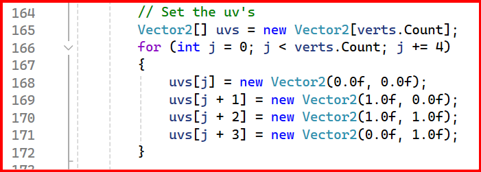
Next piece of code sets the uv’s that we want to use for texture mapping. UV’s are coordinates within then texture. As a simple example, we set TL, TR, BR, BL again. UV’s are specified as values between 0.0 and 1.0 in the U and V axis (X and Y)
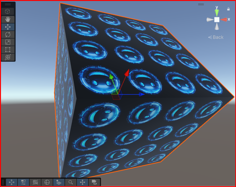
We then switch back to the TexturedMaterial to show the texture…

…and we get this…

Now, I’ve skipped through a lot of information in a short update and will be going back over a few things to clarify further.
Hope you find this helpful. If you have any questions then please add them to the comments and I’ll reply as soon as I can.
Take care,
Andy


Leave a comment