
As an example of how to programmatically generate a mesh, I’ve started with a simple programmatically generated quad. This shows the basics of 3D without going into a huge level of complexity.
First, let’s talk some basic 3D. We’re using Unity for these examples, so we’re using Cartesian coordinates to define positions in Euclidean space. What does that mean? Well, it’s a bunch of fancy words to say that we’re using X, Y, Z positions to define points (or Vertices) in a scene. Each point is part of a 3D object.
Each Vertex (point) represents a position in 3D space. A Vertex at 0, 0, 0 is in the middle of the scene. A Vertex at 1, 0, 0 is 1 meter to the right of centre in the X. By setting up batches of these vertices and joining them using lines or triangles, we build 3D objects.
So, here’s a snippet of vertices from a larger list. This is what the typical vertex list might look like in a 3D model

…each of these points represents a ‘point’ in the 3D scene. The full set of these points, when joined together using triangles, might look something like this…
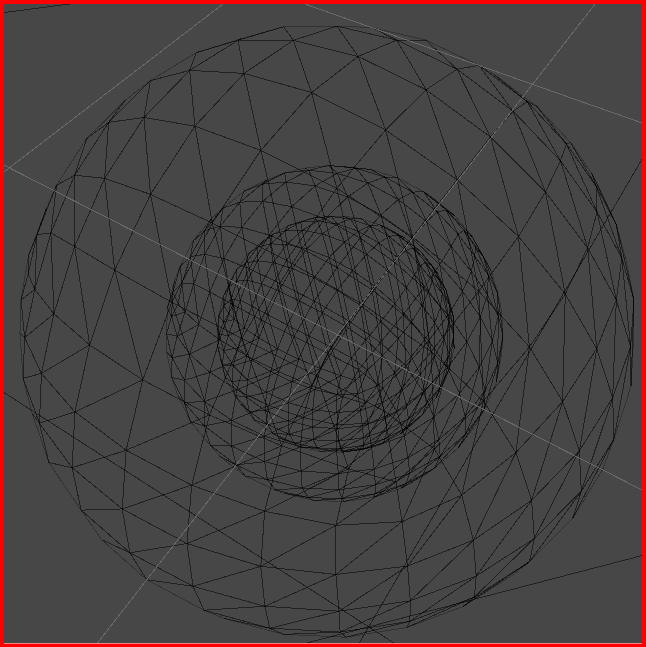
So, you can see how vertices can be turned into objects.
Obviously, there are a lot of steps to go through to build something complex, but we’ll cover each step one at a time.
For now, lets get a basic quad onto the screen. First, we’ll need vertices, then indices and then a bit of colour so we can see how the shape fits together
Here’s the initial piece of code. This bit has nothing to do with the Unity engine and could be used in any engine

So, we have a list for vertices and a list for indices.
A vertex (vertices) is a list of points in 3D space
We define only 4 points for a quad. Top Left (TL), Top Right (TR), Bottom Left (BL) and Bottom Right (BR)
A index (indices) is a list of references to the vertices. We use this second list to reduce the amount of duplication in the vertices and, ultimately, to optimize the speed of display by reducing memory usage and improving cache hits.
The colours are defines as an array of RGB (Red, Green, Blue) values that are used to colour the vertices so we can see which is which.
Now the Unity bit…
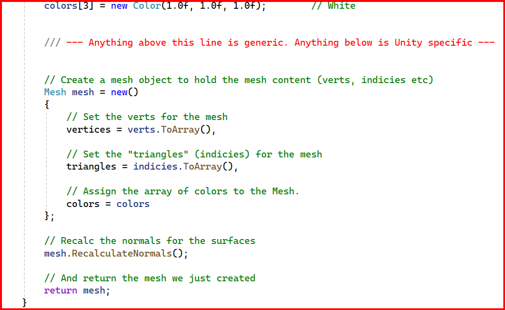
So, Unity has a Mesh Renderer, Mesh Filter and Mesh. The last one is the bit we care about for this example. We define a Mesh object and then apply the vertices, indices and colours from the previous piece of code.
One extra step is the “mesh.RecalculateNormals()”, we do this to make sure the lighting in the scene works correctly. I’ll explain that later.
When we run the code, we see this on the screen…
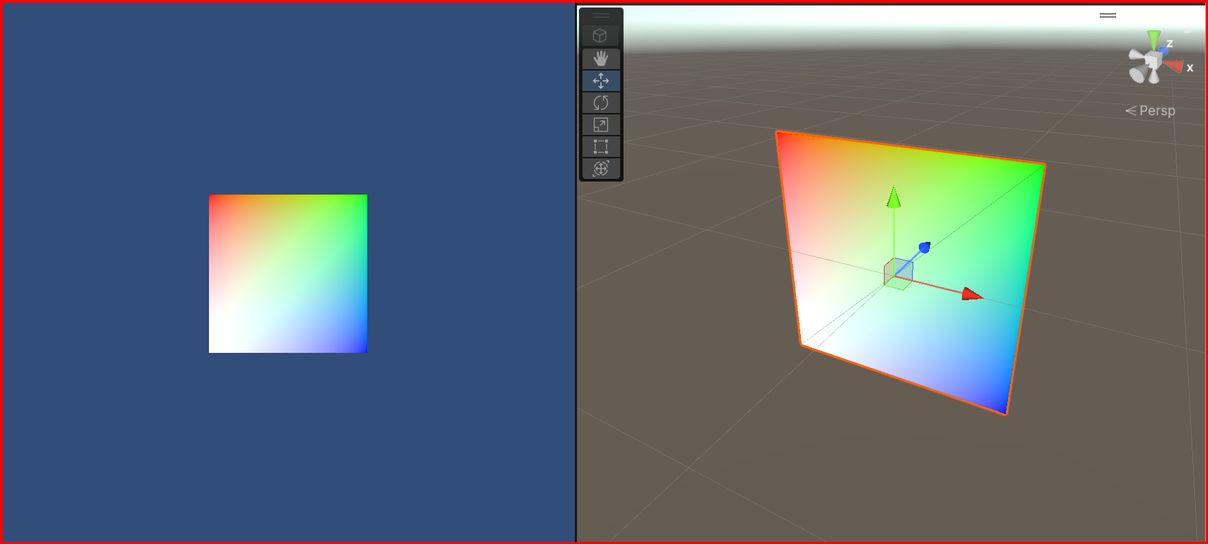
You can see the vertices each have a colour assigned. TL is red, TR is green, BR is blue and BL is white.
In the right image, you can also see the line that joins the two triangles that make up the quad. Everything you see in a 3D scene is made up of triangles
Next, we’ll talk about winding order and how the indices are being used to simplify the model display and we’ll generate a symmetrical programmatically generated cube with adjustable subdivisions…
As always, all source is available here. It’s all free to use so help yourself if there’s something you find helpful.
Please Remember: The code in the examples has been written to be show functionality. It hasn’t been optimised to the nth degree. We’ll go into optimisation in later posts. For now, this is all about learning the basics and explaining how things work. I know there are Unity methods to handle the math and the physics, but that doesn’t teach you how the math and the physics work so I’m doing everything long-hand for now. Hope that makes sense.


Leave a comment